Digital I/O
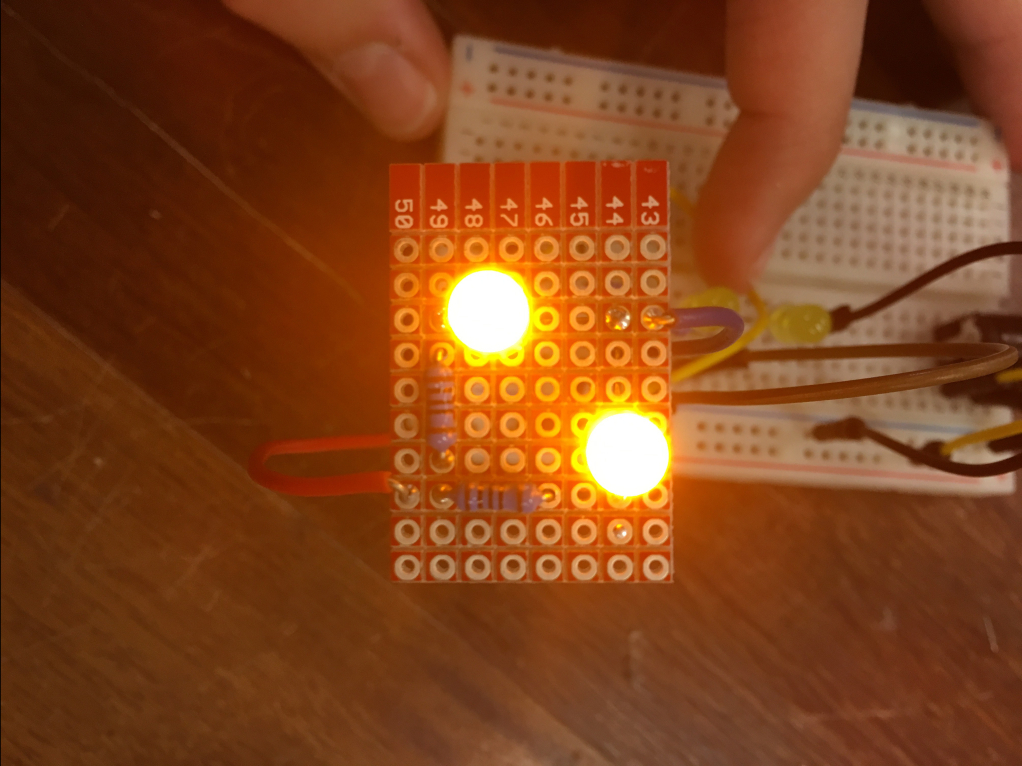
In today’s lab we started off the day with soldering. To begin we had to solder a circuit of our choosing from yesterday’s lab using two LEDs. I chose to make two LEDs in parallel circuit. For this I didn’t need a battery component to plug the power into the prototyping board and I also chose not to use a switch (however, it is possible to use the connection to the breadboard with the switch on there to be able to use the switch similar to yesterday). For the parallel circuit I knew I needed two 100 Ohms resistors, 2 LEDs, an power wire, and a ground wire. I placed my components in the node slots in the prototype board and followed the schematic shown below.
Schematic of in parallel circuit without switch.
Any time there is a node is a place where the wires crossed on the bottom of the board. I then placed the wires flat on the board so they laid parallel to the board . Once all the wires and components were in place I used the soldering iron to solder all the pieces in place. Any time there was a node, the solder would help to bridge the connection between them, similar to the terminal strips on a breadboard, allowing the electrical current to travel through the circuit.
Top side of 2 LED in parallel circuit
Bottom side of 2 LED in parallel circuit
Plugged in and lit up 2 LED in parallel circuit
When I was testing to see if the light worked when the wires were plugged in to power and ground I simply plug the wires into the power strip and the ground strip on the bread board.
The video for this circuit can be found here.
The second activity for today was working with a micro-controller, a breadboard, buttons, and neopixels to create a device that would take multiple inputs and have one output for every input. For this activity I started with developing the schematic of how I wanted to design the system is shown below:
Schematic of design
For this design I wanted to be able to use both an LED, along with a button (similar to a simple in series circuit done before) and a neopixel strip with a switch. To start the construction of this device I used connected a wire from the power supply of 5V on the RedBoard to the power strip on the breadboard. From there, I attach a wire from the power strip to the first press button. I then attached to the other side of the button a 10 kilohms resistor to the ground state on the breadboard. The ground state on the breadboard is connected to the ground state on the RedBoard. This is then repeated for the switch as well. Continuing off of developing the button that activates the LED, I attached a wire connecting to a Digital terminal on the RedBoard to a row in the breadboard. In the same row, I attached one side of a 220 Ohms resistor. The other side of the resistor was attached to a new open row where the positive side of an LED was added. The negative side of that LED was then attached to another empty row in the breadboard and then one side of a wire was added to the same row as the negative side and the other side of the wire to ground state on the breadboard. For the neopixel strip I attached one side of a wire to another port in the Digital terminal on the RedBoard and the other end to the same row as the center position on the switch. I then attached a wire from another one of the rows the switch is attached to to the ground state on the breadboard. As for the neopixel strip itself I attached the yellow wire, the middle wire, into a digital terminal on the RedBoard, and the red wire to the power strip on the breadboard and the black wire to the ground state strip on the breadboard. It ended up looking as shown below.
RedBoard Arduino Set-up
Breadboard Set-up
As for the software part of this project, I coded to have each of the pin numbers used in the Digital terminal of the RedBoard be read in when set up and then stored what state the two buttons were in (whether on or off). I then checked the condition of the buttons. If the press button was pressed and therefore on, then the LED light would light up, otherwise it would be off. If the switch was switched to on, it would cycle through a rainbow function that made the neopixel strip cycle through colors, otherwise, it was off. The code I used is shown below.
The final video of the project running is shown here.


